The Solution
A tool that is easy to use to measure the air fuel ratio in an individual combustor offers significant advantages in that it can allow fine tuning of air and fuel flows so that each combustor canister is optimised leading to improvements in emissions and overall engine performance. By using of the shelf optical components SCITEK has produced a probe that was successfully used in the harsh environment of a combustion chamber of an industrial gas turbine under gaseous and liquid fuel operation. This probe was made to withstand temperatures of up to 700 deg C and by collecting light in the UV spectrum it can track and measure emissions from OH and CH species the ratio of which is known to be air-fuel ratio dependent. Air fuel ratio also tends to influence temperature.
The SCITEK system is capable of measuring variations in the burned gas temperature arising from air and fuel flow rate variations. This will be based on the measurement of the light intensity emitted from the OH (310nm) and CH (430nm) species, the ratio of which as mentioned earlier is temperature dependent. The measurement system is not intended to deliver an actual temperature or equivalence ratio but is to detect levels in each individual combustor canister which can then be compared with each other to determine variability in individual combustor performance.
The probe head is normally custom designed and made by SCITEK to suit combustor geometry and customer requirements. Much of the hardware such as the spectrometer and fibres are proven technology bought off the shelf. Software for processing spectra is also off the shelf and is provided as part of the probe system. It is the coupling of the fibre to the combustor that will be a bespoke probe.
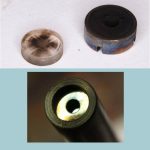
The main challenge in using this probe is to maintain the probe window suitably clear of soot during testing. For gas fuelled engines the end of the probe stays reasonably clean but. However for liquid fuelled engines purge air should be used to prevent soot from depositing on the probe window. Although some soot will inevitably be deposited on the window it still allows measurements to be carried out.
The two images above show that the window eventually gets deposited with soot but not enough to stop valid measurements and the use of purge air extends significantly the experiment window. Purge air also helps keep the window cool enough to withstand the heat from the combustor during operation.
About the Project
SYSTEM COMPONENTS
The components supplied with this system include :
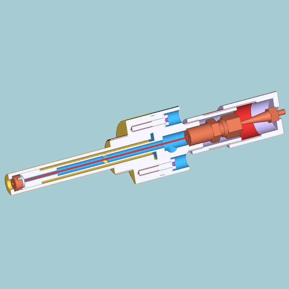
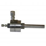
(1) The light collection probe and fibre coupling to suit combustor geometry. The probe also ensures that high pressure air from the combustor cannot be exhausted from the probe to the outside. A fused silica window is fitted to act as a barrier between combustor and fibre optic sensor which is cooled with compressed air. Note, that amount of purge air is small in comparison with quantity of air going through the combustor. A suitable fitting is used to hold inside the probe a high temperature fibre (see item 2) ensures that the fibre is gas tight inside the probe and also acts as a second barrier in the event the sapphire window breaks.
(2) Two high temperature (700 deg C) gold buffered optical fibres for UV and visible wavelengths. The fibre is used to collect light from inside of the combustor and channel it to spectrometer. Note that two fibres will be supplied one will serve as a spare in case the one installed in the probe gets damaged during installation or during use.
(3) Single 20m fibre extension to connect high temperature fibre to spectrometer. UV compatible
(4) Single channel spectrometer for UV and visible wavelengths with a USB interface.
(5) Software that allows configuring and running the spectrometer for data recording and analysis of flame spectra.
IMPLEMENTATION
The probe can be used in aero and power generation gas turbine engines. In both cases the end of the probe is designed to be flush with the combustor wall so that it is not exposed to the flame or to the high temperature gas stream in the combustor.
Of course the temperature inside the combustor is much higher than the temperature rating of the probe but by making it flush to the combustor wall it is not exposed to the flame temperature.
As stated above the probe makes use of gas cooling so that its temperature is maintained to within acceptable limits. If required by the customer the probe can also be fitted with thermocouples so that internal temperatures can be monitored but this adds to complexity and cost and depends very much on the application.
In aero-engine gas turbines the probe should be fitted in a way that it is exposed to cooling air that is fed to on the outside of the inner combustor chamber skin which helps keeps its temperature within limits.
In land based engines the probe is designed to fit inside one of the spare igniter ports and this arrangement helps keep the probe temperature within limits as it is surrounded by a significant amount of metal.
The most vulnerable parts of the probe to high temperature are the optical fibre and the fused silica window and the upper temperature limit is therefore based on these components.
It must be stressed that this probe is a research tool and not a sensor that can be permanently installed on an engine and last for thousands of hours. Thus in order to ensure longevity use on the engine should be short and removed when they are not needed. Spare optical fibre and glass window are provided with each probe as these will deteriorate with use and will eventually need replacing.
REFERENCES
(1) Chemiluminescence Based Sensors for Turbine Engines by T.M. Muruganandam, B. Kim, R. Olsen, M. Patel, B. Romig and J.M. Seitzman. AIAA 2003-4490, 2003.
(2) Detection of Temperature and Equivalence Ratio in Turbulent Premixed Flames Using Chemiluminescence by R.J. Romy, J.E. Reaney and E.L. Johnsson. Proceedings of the 1998 Int. Joint Power Genertion Conference, Vol. 1, 1998