The Challenge
To design and manufacture a hydro mechanical test rig that can be used in the commissioning of aero engine fuel supply and control systems.
Find out how SCITEK tackled this challenge below.


To design and manufacture a hydro mechanical test rig that can be used in the commissioning of aero engine fuel supply and control systems.
Find out how SCITEK tackled this challenge below.
The rig needed to be capable of testing fuel systems ranging from those used on small business jets to those used on large engines powering long haul jumbos. The rig needed to have increased functionality to improve testing efficiency and reduce downtime.
The main purpose of the rig was to flow Kerosene through the fuel system components at a range of pressures, temperatures, and fuel flow rates accurately replicating conditions that the engine will experience in a flight cycle operated in different parts of the world.
The entire rig had to be contained within a pre-determined space envelope, yet still achieve target removal and installation times of major components during maintenance so that rig down time was as short as possible.
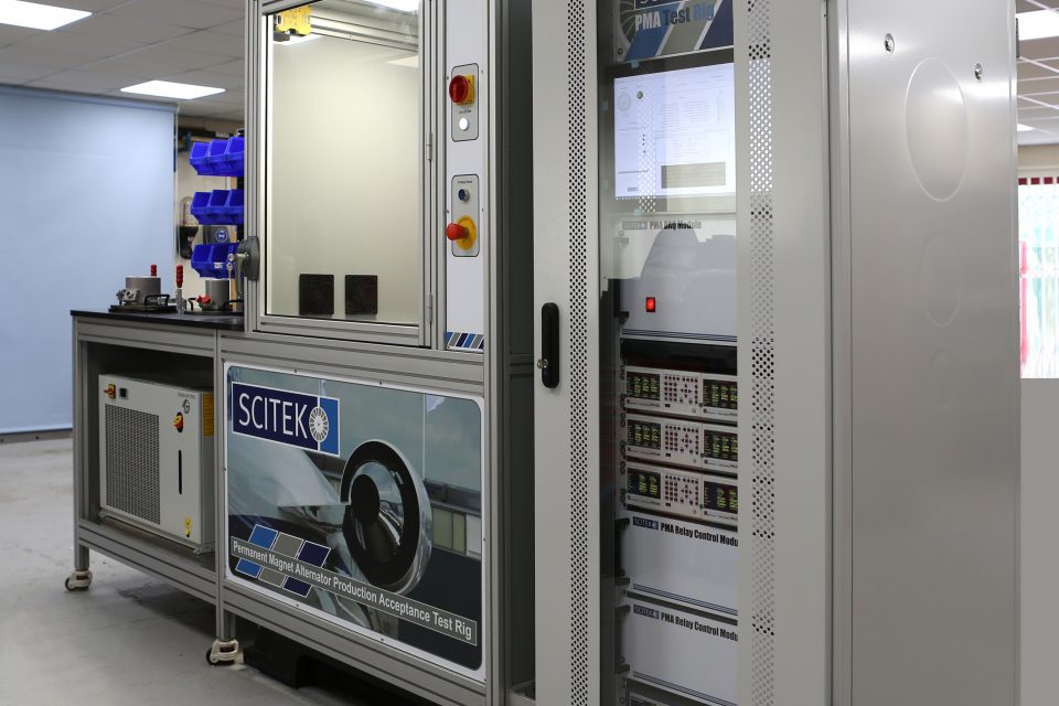
A hydro mechanical test rig that featured a variety of fuel circuits to allow it to be used with a wide range of Engine Control Systems. The fuel was directed through flow meters, control valves, and heat exchangers to meet the requirements of a specific test cycle.
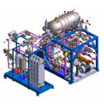
A detailed 3D CAD model was generated during the design process to ensure correct routing of all pipes and location of all components and instrumentation. This also helped ensure target removal and installation times could be met.
The rig was finally manufactured and installed at the customer’s site and proved to be a considerable improvement to previous rigs with regards to utilisation of space and in long term maintainability and serviceability of the the facility.
The Fuel Test Rig had to use components that were capable of meeting the following conditions:
•Flow Range = 0 – 10,000 imperial gallons per hour
•Fuel Pressure = 1.5psia to 3000psig
•Fuel Temperature = -55 to +200°C
•Pump Drive speed = 0 – 15,000rpm
The fuel circuit comprises of the following modules:
1. Fuel Tank
2. Filter Loop
3. Boost Pressure Loop
4. Throttle Valves (Burner Simulators)
5. Flow meter Banks
6. Hot Loop (Fuel Temperature up to 200°C)
7. Cooler Circuit (Fuel Temperature down to 0°C)
8. Chiller Circuit (Fuel Temperature down to -55°C)
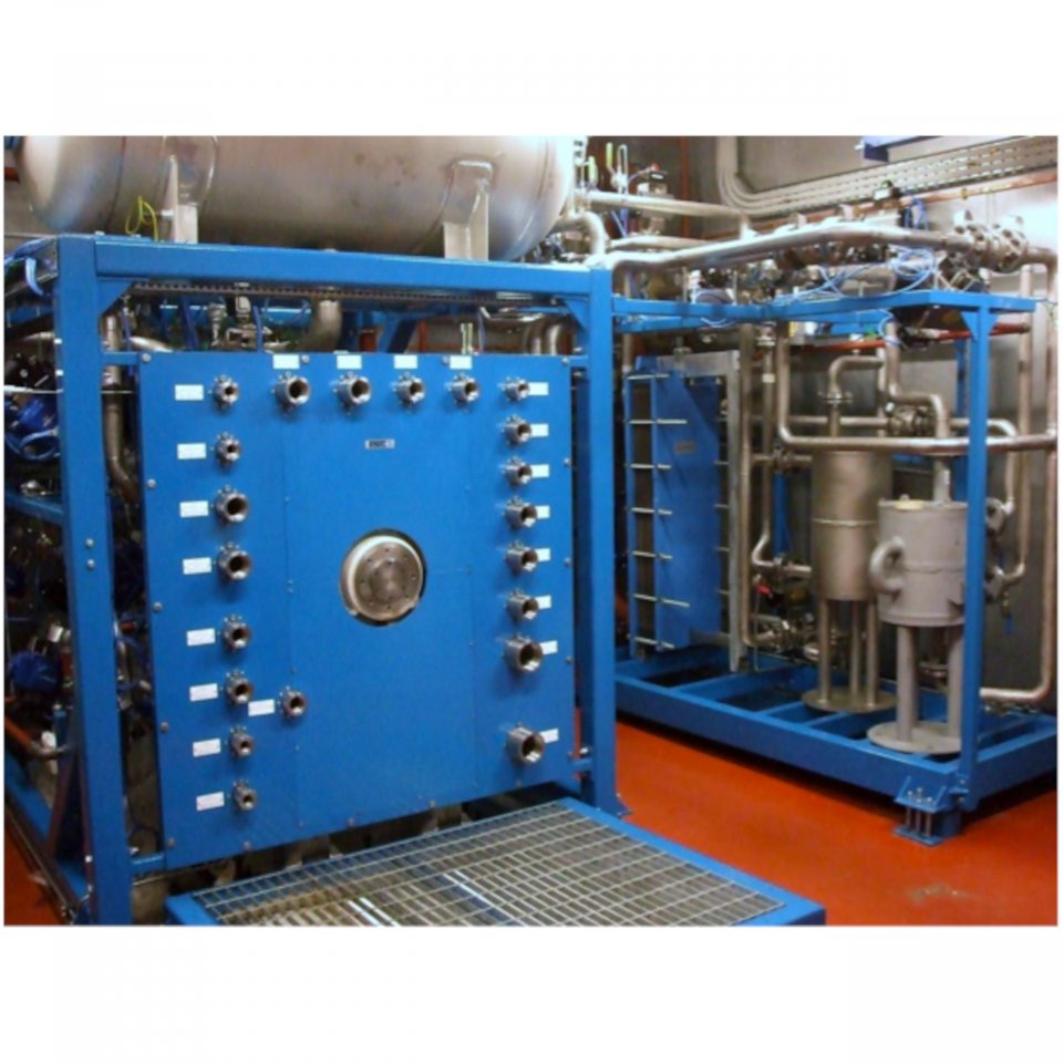
All of these modules were bracketed to a main support frame and auxiliary sub-frame assembly, with each circuit terminating at a common bulkhead. The rig was divided into two skids, the main fuel skid which housed the majority of the components including the tank, and a smaller heat exchanger skid alongside it.
To boost the supply pressure of the fuel to the unit under test, a boost pump was located behind the drive support frame, low to the ground, and fed by the fuel tank located on top of the main support frame.
The rig is now in daily use for the testing and certification of aircraft fuel components.
Contact us now to find out how we can support you with your testing needs and innovations.